|
EtherPPS 0.01 (IPv6 access)
The EtherPPS project is two parts: A program for a microcontroller that converts a pulse signal into an
ethernet frame, and a daemon that talks to ntpd. This allows using a spare ethernet nic as
a PPS input, and provides kenel timestamps without a pps kernel and serial/parallel ports.
download netpps daemon source (builds on Linux. Hacked version of shmpps. Very much Alpha)
download EtherPPS *VR source & prebuilt versions (packet configuration tool requires Windows/Wine)
download a crude debugging listener (receives debug and frequency information)
EtherPPS implements ethernet transmit in software. Unlinke a conventional ethernet controller the latency and
jitter of the system is well defined. In particular it generates a frame with
controlled end time, thereby controlling the PPS-to-interrupt
delay.
The prototype was tested by feeding an NTP server with the same
PPS signal through RS232 and EtherPPS. The known latency of the
EtherPPS (from PPS input to last bit of the frame CRC) is subtracted out automatically by the receiver code. In addition
to the directly connected case, various 'degenerate' setups were tried. It turns out that even the suboptimal setups beat NTP-NTP
sync by a large margin, making it feasible to get sub-50us sync on all nodes on the network.
| Test setup | Delay | Jitter |
| RTL8100, dedicated nic | -6µs* | 4µs |
| RTL8100, shared nic, HP 1800 switch, priority tagged multicast, heavy load | -5µs* | 4 µs |
| RTL8100, shared nic, HP 1800 switch, no priority tags, net radio. | -3µs* | 8µs |
| Pro/1000GT, shared nic, HP 1800 switch, priority tagged, net radio, D945GCLF | | 9µs |
| +modprobe.conf: options e1000 InterruptThrottleRate=0 | -5µs* | 1µs |
| +modprobe.conf: options e1000 InterruptThrottleRate=70000 | | 5µs |
| Shared nic, 6 hop corporate network, site to site on a priority tagged vlan | +14µs | 18µs |
| Serial port DCD strobe (reference) | "0" | 4µs |
| Hardware timestamping of the EtherPPS output (relative to predicted) | +15 ns | 17 ns |
|
*: negative numbers indicate that the nic input has lower delay than the RS232 port. For the switched tests the theoretical packet
length on the additional links was subtracted. |
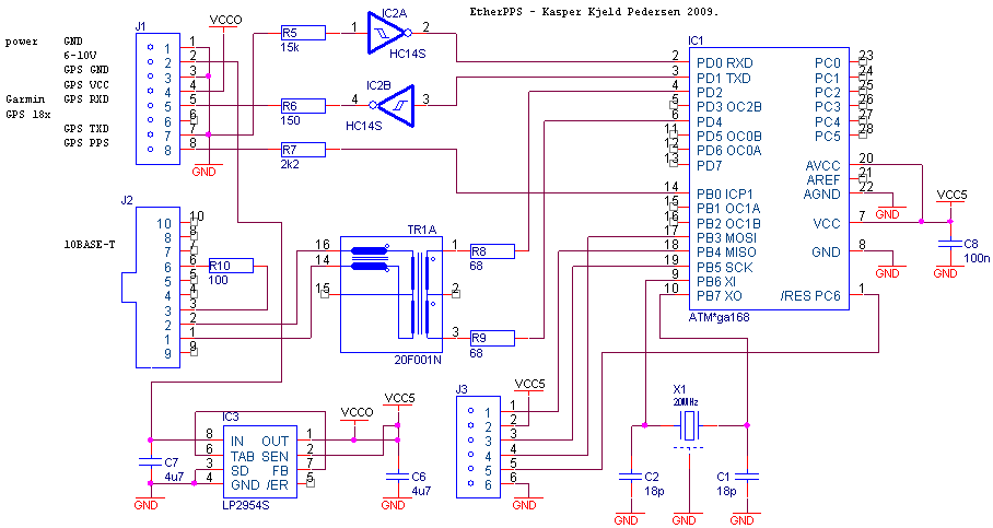
(pdf copy here. The current code does not actually implement UART
functions, so the RXD/TXD inverters can be omitted if you're only after pps.)
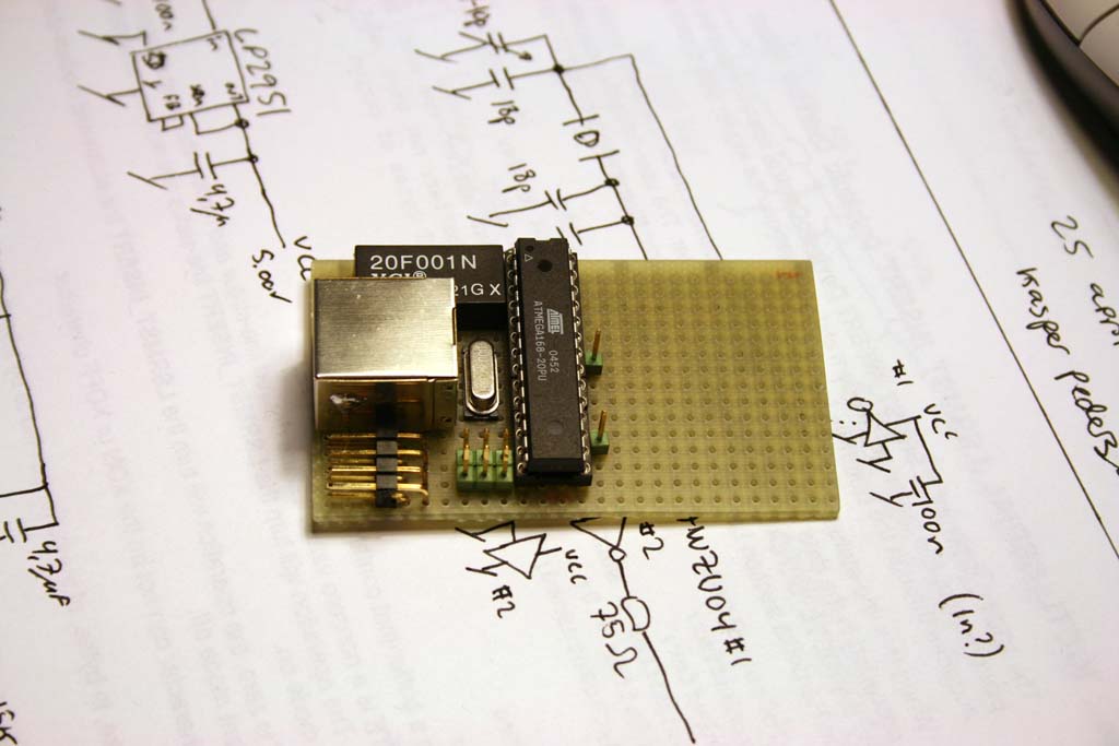
(here's a photo of the prototype)
Configuring the microcontroller firmware
The firmware may be built with priority tagged frames, vlan frames, multicast or
broadcast, different port numbers, and different source
addresses. In addition to generating a PPS frame, the firmware
can run a 'telemetry channel' and transfer uart and pps timestamp
information to the host. The secondary channel can have different
destionation, different vlan, priority, and so forth. Also the
firmware has a guard interval around the PPS frame, thereby
making the ethernet port idle, and able to achieve 55 ns peak to
peak jitter on the PPS frame in the presence of telemetry frames.
A PPS frame is also sent on the telemetry channel. It is delayed 200µs
compared to the PPS frame; Thus if you configure the main PPS
frame for 500µs, the telemetry-PPS is set to 700µs.
One scenario where this is useful is when the PPS frame is a vlan
tagged, high priority multicast frame that goes into the client
network, while the telemetry data is similarly tagged multicast
to the timeserver's PPS-dedicated network port. With proper
selection and configuration this adds ~1µs jitter, while at
the same time allowing clients on the LAN to maintain
synchronization only slightly worse than the main timeservers (in
practice within 25µs) and better than achievable with NTP.
Frame formats
Each frame contains only 8 bits of payload. The frame is a UDP packet
sent with the parameters found in the gen.cf file, which is read by
generatepkt to produce the packet source file. The UDP payload is 40 bytes,
8 groups of 5 bytes each. The most significant bit of the first byte in
a group of 5 bytes is a payload bit. The first payload bit is the least
significant bit. The 32 bits following the payload bit is a CRC compensation word.
All generated packets of a particular type have the same ethernet checksum.
The PPS packet encodes the delay between the PPS pulse and the completion of the
transmitted packet, delay=n*500µs for n=1..31, resulting in 0.5..15.5ms.
Receiver software can use this value to subtract out the PPS delay.
A value of 0 indicates a PPS packet sent with the same delay as other PPS packets
from the device, only the time stamp is not dependable (not currently used).
The telemetry packet also carries only one byte, but the sequencing is important:
0xBE is a PPS mark. It is delayed 200µs
compared to the PPS packet.
0xBD is an escape character. The sequences are:
0xBD 0x14 ts3 ts2 ts1 ts0 pdc is PPS information about the previous PPS event.
ts is a 32 bit big endian timestamp of the PPS edge against the cpu clock with 50ns resolution.
pdc is the same byte as sent in the PPS packet, allowing the same delay compensation to be performed.
0xBD 0x15 fe3 fe2 fe1 fe0 dac1 dac0 is sent every 60 seconds, fe is the measured
(signed 32bit) oscillator error in 0.1ppb steps, dac is the VCXO setpoint. If a VCXO is not used, the dac value will be 0.
0xBD 0x00 encodes a 0xBD character received on the UART.
0xBD 0x01 encodes a oxBE character received on the UART.
Characters received on the UART other than 0xBD and 0xBE are sent verbatim.
There is a timing gap after the 0xBE marker of 100ms or more. Characters received by the UART in this period
are buffered and sent once the blanking window expires.
Attributions
The ethernet transmit code is derived from Igor Češko's IgorPlug-UDP.
The differences are rewriting to fit GCC, standards-compliant NLP transmission,
802.1Q tagging, and getting rid of the mid-packet CRC32 compensation word.
Known things to do and not to do
Intel PRO/1000 CT does not like InterruptThrottleRate=0 (hangs), use 70000 instead.
Intel PRO/1000 pci-e adapters directly connected to EtherPPS: use Duplex=2 Speed=10 to avoid syslog messages
When a switch is involved, DO set the port where EtherPPS is connected to forced 10FDX. This means no unmanaged switches
Really old PRO/1000 with 82541EI chips have a hardware bug in multicast filtering. GI/PI are OK.
Do not run PPS frames over the plain network at plain priorities. In order to
pass PPS frames useful to NTP and faithful to the NTP RFC there
has to be bounded latencies. In an ethernet this means only using
priority aware switches in the path, only switches with specified
maximum latencies, reserving the highest priority queue for PPS,
and possibly a dedicated nic in the server. If interrupt throttling is
disabled to remove the ~5 µs throttling introduces,
the interrupt load can become significant if the machine also performs 'bulk data' functions.
If the machine is acting as an NTP server with such high performance that 5µs matters,
NTP should run over either the PPS nic, or over a separate nic with throttling likewise disabled.
Do not attempt to use unmanaged switches for EtherPPS if you intend to use the telemetry channel.
EtherPPS' link partner must be manually set to 10FDX since EtherPPS doesn't implement CSMA/CD.
GPSDO version of EtherPPS
The source for EtherPPS includes the ability to drive a VCXO. When this is just the default internal
crystal oscillator, 10s performance of ~50ppb is feasible. With a good OCXO the limit becomes the crude
15.7 bit pwm dac and the voltage regulator. The VCXO must have 1ppm trim range, otherwise the code can
not do df/du gain autotuning.
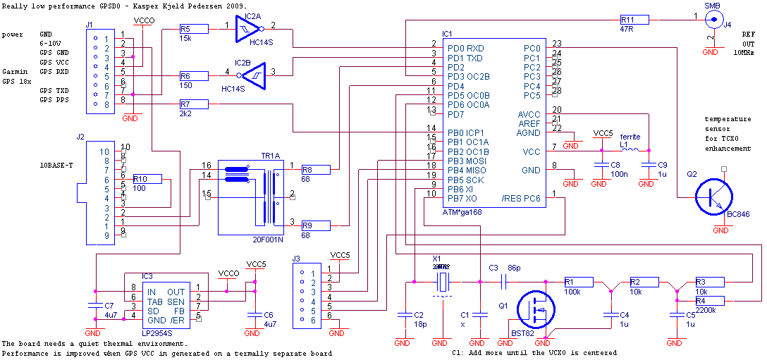
(pdf copy here)
|