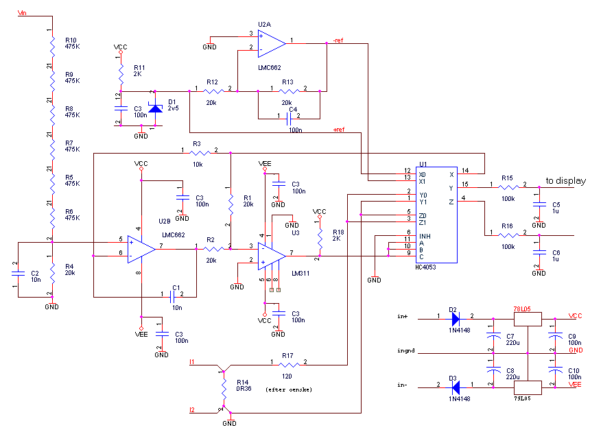
One solution is to use a microcontroller and A/D converter and do it in software, but that's a lot of work and somewhat expensive.
The solution presented here achieves extremely good zero (limited only
by thermocouple effects), operation to DC with 0.1% error, and AC operation
with 0.15%. There are no temperature sensitive analog components, multipliers
or similar, that require extra care. The downside is that the voltage input
bandwidth is limited to a few kHz.

Circuit description:
The reference voltage is generated by D1 (In my case a selected LM336-2.5),
2.5V. U2A produces an inverted reference, -2,5V, so I now have a reasonably
stable bipolar reference. This reference is used as an input to the integrator
and schmitt trigger U2B/U3: With the input 0V, and the comparator initially
1, the integrator will ramp up until it's output voltage equals the referene
voltage. Then the comparator will flip, and the integrator will ramp until
its output voltage equals the negative reference. The ramp speed is controlled
by the input voltage, thus we have a linear relationship between input
voltage and duty cycle of the comparator. At 0V this is very close to 50
%, and if the device is to be used at DC, the offset of the amplifiers
can be removed by trimming the negative reference.
The duty cycle output also drives the shunt inverter: when high the
shunt is connected one way, when low it's connected the other. Because
the duty cycle is matched to the voltage, we get a four quadrant multiplication
when we average the output.
It is intended to be used with a typical 9V panel meter (high impedance differential input, powered from VCC/VEE)
Since this instrument lives on the power line, use a cat- kid- and poke-with-screwdriver proof enclosure.
Design notes:
With the shown components the integrator rate is 0.025V/us, staying
40x below the slew rate limit for LMC662, and giving 2500Hz chop frequency.
If you desire higher chop frequency - 25kHz would be good for a lab instrument
- use a faster opamp for U2B, and use a faster comparator.
The choice of HC4053 (in my case a Philips part) over the old 4053
(15V-CMOS) is required in order to operate without buffers on the output
of the multiplexer.
C2 does give a phase shift, and does introduce a small error, but it's
better than having high frequency noise ruin the integrator.
I recommend placing a pair of 3.6V zeners back-to-back at the multiplexer
to catch transients from the shunt. This is useful when using the instrument
on switching supplies.