|
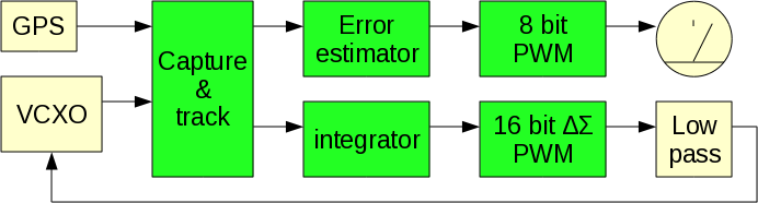
SimpleXDO 0.02 (IPv6 access) SimpleXDO is a small piece of code for an ATTiny13 microcontroller. It forms a phase locked loop between a reference source and a voltage controlled oscillator, and keeps state over power cycles.
download simplexdo.asm (avrasm2) It is intended for use in simplistic GPS diciplined oscillators, and for self calibrating oscillators in radios and measurement equipment. It will lock to any integer input frequency in the 1Hz-100kHz range, generate a 39kHz PWM signal with 16 bit resolution for frequency control, generate a frequency error estimate with 0.4 ppb resolution and +/-50 ppb span, store DAC value to eeprom at 27 minute intervals, and dump DAC, timing, and frequency error to a serial port. PPS handling in this design is delayed, in that it will not adjust the DAC until the input pulse train has been stable for 256 seconds, and once tracking, it does not use the arrival time of a pulse until the pulse one second later has been found to be valid. This makes it safe to connect and disconnect PPS sources, as well as power cylce at random. When power is applied, it will restore DAC settings from eeprom, and wait for PPS.
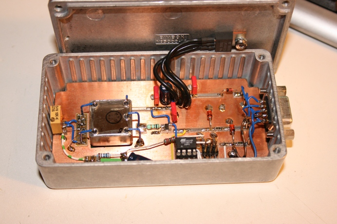
External components for the test setup: The PPS source can be anything that emits an integer frequency in the 1Hz-00kHz range, and at least 600ns wide. For the test setup I used a non-timing Garmin GPS18X, as well as PPS from a rubidium reference. The test oscillator (left) is a low cost 1ppm TCXO with 5ppm tuning range. It should be noted that the capture range is 2ppm max, so the TCXO needs to be pre-adjusted to be within capture range. The time constant is set to 54 minutes since the PPS output from an indoor GPS18X isn't exactly optimum, and the GPS18X is configured to turn off PPS when fix is lost.
The low pass filter (bottom) on the delta-sigma PWM is 22k/180uF, a time constant of 4 seconds. This means that after power-up one should wait 40 seconds (10 tau)
before considering the output stable. tau should be less than 25 seconds in order for the DAC voltage to be stable before disciplining starts. The output from the TCXO is buffered, to isolate the TCXO from loading effects, as well as allow it to drive a cable. Loop information is dumped at 38400N81 to minicom, captured to file, passed through conv (above), and then through gnuplot.
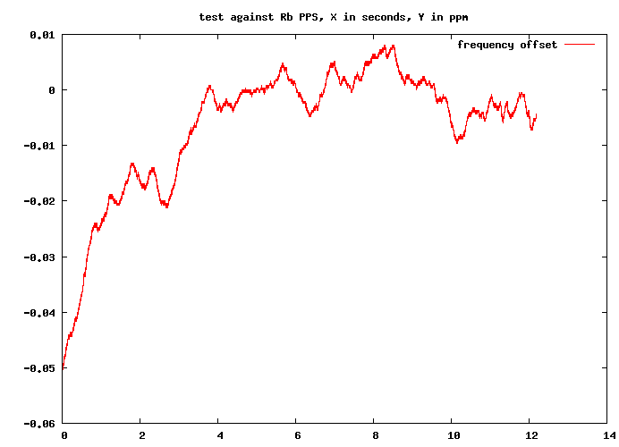
Below a plot of operation with 54 minute time constant. Keep in mind that this a TCXO, not an OCXO.
And yes, the X axis is in hours not seconds.
|